Using Torsion for Controllable Reconfiguration of Binary Nanoparticle Networks
Last updated on
May 15, 2021
Collaborators
Tao Zhang, Badel L. Mbanga, Victor V. Yashin, and Anna C. Balazs$^*$
Chemical Engineering Department, University of Pittsburgh, Pittsburgh, Pennsylvania 15261$^*$E-mail: balazs@pitt.edu
Motivation
Mechanical deformation can potentially provide an effective means of controlling the nanoscale morphology in hybrid materials. The challenge, however, is establishing optimal couplings of the deformation and mechano-responsive components within the material to achieve nanoscopic structural reorganization without causing catastrophic damage. In hybrid materials, polymers introduce the needed degree of flexibility and mutability; when combined with the appropriate mechanical deformation, this mutability could provide a means of reorganizing solid nanoparticles into useful structures.
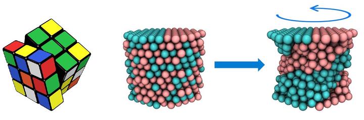
Here, we take inspiration from the early Rubik’s cube, where individual colored blocks were held together by elastic bands; by twisting the structure, the blocks moved to form a new, stable arrangement of elements in the cube. To design an analogous mechano-responsive system, we focus on polymer-grafted nanoparticles (PGNs), where each rigid nanoparticle core is decorated with a corona of polymer chains. The free ends of these chains encompass reactive functional groups that allow the polymers to form “arms” between neighboring particles and thus, interconnect the PGNs into a network. In effect, these polymer arms act as the elastic bands and the nanoparticles correspond to the individual blocks in the toy. Using computational modeling, we have undertaken preliminary studies to show that by applying torsion to this material, we can achieve significant control over the arrangement of a binary mixture of nanoparticles and hence, tailor the nanostructure of the composite.
Approach
Herein, we introduce both A- and B-type nanoparticles, which encompass different reactive groups at the free ends of the grafted chains. The energies of the labile bonds formed between the same types of particles, $U_{AA}$ and $U_{B}$, are taken to be different than the bond energies between dissimilar types of particles, $U_{AB}$. For simplicity, it is assumed that $U_{AA}=U_{BB}≡U_{AA,BB}$ . We focus on the behavior of the binary PGN networks under applied torsional deformations.
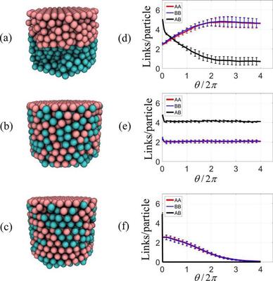
Morphologies obtained after four rotations of the top layer during torsional deformation of PGN networks formed from 1:1 mixtures of A (cyan) and B (pink) particles interlinked by labile bonds having the following bond energies: (a) $U_{AA,BB}=39k_{B}T$, $U_{AB}=33k_{B}T$, and (b) $U_{AA,BB}=U_{AB}=33k_{B}T$. In (c), the PGNs are interlinked by permanent bonds with bond energies of $U_{AA,BB}=39k_{B}T$, $U_{AB}=33k_{B}T$. The initial conditions correspond to random binary A/B mixtures within the bulk of the material; the bottom and top layers consist of solely A and B particles, respectively. (d)-(f) Evolution of the numbers of AA (red), BB (blue), and AB (black) links per particle as a function of the rotation angle $\theta$ for the systems shown in (a)−(c), respectively. The results are obtained by averaging over eight independent simulations and the error bars represent the standard deviations from those averages.
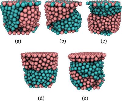
Typical morphologies obtained after four rotations during the torsional deformation of initially random 1:1 mixtures of A and B particles within the bulk. In (a)−(c), both the bottom and top layers consist of 1:1 mixtures of A and B PGNs. In (d) and (e), the bottom layer consists of 1:1 mixtures of A and B PGNs and the top layer is formed solely from B particles. The particle coloring is the same as in Figure 1. The PGNs are interlinked by labile bonds with energies of $U_{AA,BB}=39k_{B}T$ and $U_{AB}=33k_{B}T$. Note the formation of horizontally layered structures in (b)−(e).
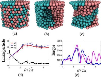
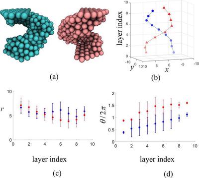
Structure formation in the course of torsional deformation of 1:1 mixtures of A and B PGNs at both the top and bottom layers consisting of the semicircular A and B patches. (a) Initial random configuration. (b) The columnar morphology formed after two revolutions of the top layer. (c) The helical morphology formed after three revolutions. (d) The evolution of the numbers of AA (red), BB (blue), and AB (black) links per particle as a function of the rotation angle $\theta$; averaging is performed over eight independent simulations. (e) Torque variations in the course of torsion deformation obtained during two independent simulations. Particle coloring in (a)−(c) is the same as in Figure 1. The labile bond energies are the same as in Figure 2.
Details of the helical structure formed under applied torsion. (a) The clusters of A (cyan) and B (pinks) particles in Figure 3c shown separately. (b) Spatial distributions of the centers of mass of A (blue) and B (red) particles in the system shown in Figure 3c and sliced into nine layers, with the top and bottom particle layers excluded. (b) Radial distances from the sample axis, and (d) angular positions of the centers of mass of A and B particles as a function of layer number obtained by averaging over eight independent simulations.
layred
random
helical
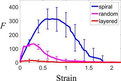
Force vs strain curves obtained from the tensile deformation of the binary PGN networks. Here, the pink line is for systems where the applied torsion results in formation of random mixture of particles (as in Figure 3a); the blue link is for systems where the applied torsion leads to helical structures (as in Figure 3c); and the redline is for systems that form a layered structure (as in Figure 1a). Averaging is performed over eight independent simulations.
Acknowledgments
We gratefully acknowledge support from the DOE through CBES, an EFRC at Northwestern University, and the AFOSR.